When designing the cooling system and pipeline of the medium frequency induction heating furnace, we should pay attention to the following aspects:
1) Use copper pipes and stainless steel pipes as pipeline materials to prevent rust chips from entering spare parts. In recent years, plastic tanks have also been used as cooling water tanks, and plastic pipes that meet pressure-resistant requirements have also begun to be used in water systems.
2) The diameter of the inlet and outlet pipes should be designed based on the actual inlet and drainage volumes. The water inlet pipe is a pressure pipe, and the water outlet pipe can be divided into a closed return pipe and a self-pressure return pipe. The former has pressure and the pipe diameter can be relatively smaller; the latter has no pressure and the pipe diameter is much larger. The quenching cooling medium displacement is intermittent for one-time quenching parts, while the scanning quenching part lasts for a long time, as well as filter resistance, etc., which must be taken into account. I have seen that many quenching machine discharge ports are designed to be small, which is related to the failure to take these factors into consideration.
3) Try to avoid contact with the air with the cooling water to avoid reducing the cooling effect of the water due to bubbles in the water. This is especially important for sensors with high current carrying density.
4) The capacity of the cooling tank of the medium frequency induction heating furnace should be considered according to specific conditions. Under the condition of a heat exchanger, the minimum cooling tank capacity should also ensure that its capacity can fill the output pipe and there is sufficient storage capacity. The empirical data is that Requires 3 -4 times the cooling water flow rate per minute.
The larger the capacity of the cooling water tank, the better the heat dissipation conditions, which can reduce heat exchange consumption, but takes up more production space.
5) Cooling water temperature control. The lower the cooling water inlet temperature is not, the better, because if the inlet water temperature is too low, water droplets will condense on the surface of the cold components (sweating phenomenon), which will reduce the electrical insulation performance and cause malfunctions. Therefore, the cooling water inlet temperature should be close to room temperature, but should not be >28°C.
6) The pressure of the cooling water depends on the cooling components and can be controlled through the shunt valve. Generally, sensors have the highest cooling water pressure requirements, while other electrical appliances require lower water pressures. Especially for oscillation tubes of high-frequency electronic tube equipment, the anode cooling water pressure is generally greater than 0.12MPa, less than 0.2MPa, etc., and must be configured according to the instructions. The outlet temperature of the cooling water should also be monitored according to relevant instructions. Generally, when the temperature rise is too large, it is often a fault state, and the outlet water temperature should generally not exceed 55°C.
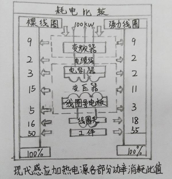
7) Heat transfer amount of heat exchanger. The heat transfer amount of the cooling water system heat exchanger is related to the equipment's power usage, load coefficient and the efficiency of certain components. Due to the improvement of conversion efficiency of variable frequency power supply, for example, the efficiency of solid-state power supply is 90% to 95%. Therefore, the power of the hot plate equipment generated by the equipment is 10% (except for high-frequency tube equipment); the bus loss is <5%; the capacitance loss is approximately 2%; the quenching transformer loss is 11%-15%; the inductor loss is about 21%; and the power obtained on the workpiece is between 50%-55%. The picture above shows the power consumption ratio of each part of the modern inductor heating power supply.
It can be seen from the figure that the required power capacity of the cooling water system heat exchanger of the medium frequency induction heating furnace is 45% of the power supply, while the required power capacity of the quenching water system heat exchanger is 55% of the power supply, that is, a 10OkW modern frequency conversion power supply. If running at full power, the heat exchanger capacity of the equipment cooling water system should be 45kw (38718kcal/h). The heat exchanger capacity of the quenching water system should be 55kw (47322kcal/h). In fact, the load rate of 99% of the full power is very rare. Therefore, the above capacity should be multiplied by the coefficient K (K<1), which is determined according to the used power and load rate.
8) For pipe fittings in a system, try to use the same metal, otherwise the pipes will suffer from electrical corrosion.
9) The arrangement of pipelines must be neat and orderly, and bends must be minimized to reduce resistance. In addition, the multiple water supply pipes from one distributor should be of equal length to ensure uniform spraying.


 en
en  cn
cn  jp
jp  ko
ko  de
de  es
es  it
it  ru
ru  pt
pt  vi
vi  th
th  pl
pl 


 GS-ZP-1200


