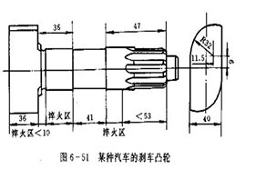
The shape of the brake map of a certain car is shown in Figure 6-51. It has three places that require induction hardening, that is, one cam and two journals. Automobile cams mostly use 45 steel forging blanks, and the cams are broached on a broaching machine. The surface hardness of induction hardening requires HRC52-63, the entire surface of the cam part is hardened, and the depth of the hardened layer is 1.5-5.0mm. The depth of the hardened layer at the neck part is 1.5-3.5mm.


The journal part can adopt simultaneous quenching method or continuous quenching, and quenching can be realized by using conventional simultaneous heating quenching inductors or continuous quenching inductors. The induction hardening of the cam part is a little difficult. Here we will introduce it emphatically. It can be heated and quenched by two kinds of inductors at the same time, and each has its own characteristics.
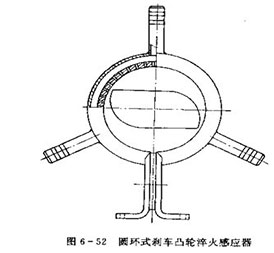
(1) Annular sensor quenching technology
Using the inductor shown in Figure 6-52, the diameter of the effective circle. The effective full width of the induction is equal to or slightly larger than the width of the cam. The quenching characteristics of the inductor are: simple operation, difficult adjustment of process parameters and the need to use a large-capacity medium-frequency induction heating machine.
There are left and right brake cams, and the directions of the cam curves of the two are completely opposite. When the journal is upright and the cam curves are observed, one is left-handed and the other is right-handed. When the ring sensor is used, the left and right brake cams can be placed in it, and the same specification can be used for simultaneous heating and quenching at intermediate frequency. For example, if the center axis of the sensor is effectively complete and the contact plate, there is a center top made and used for positioning under the effective ring, and a V-shaped positioning block that can lean against the journal is installed on the effective ring. This design makes Both the left and right brake cams can prevent the sensor from being centered, and lean against the V-shaped block. The parts are splashed and positioned very conveniently. It does not matter whether the front and rear brake cams or the left and right brake cams can be quenched with one sensor.
Due to the large gap of this inductor, it is difficult to adjust the quenching specification. A large-capacity medium-frequency induction heating machine must be used to adjust a barely usable process specification.
Now analyze the rationality of the above process parameters. The rated power of the medium frequency induction heating machine is 200KW, but now the output power is only 118KW, accounting for only 59% of the power supply capacity, and the specific power of the parts is less than 1.0KW/cm3. The specific power of the parts is still less than 1.0KW/cm2. It can be increased further, while shortening the heating time to improve production efficiency. But no matter how it is adjusted, the output power cannot be increased. The reason is that the gap between the sensors is too small and the electrical parameters of the intermediate frequency cannot be adjusted. Judging from the small intermediate frequency current, it seems that the turn ratio of the quenching transformer is too high; if the load voltage drops, the voltage will be larger, and it seems that the turn ratio of the quenching transformer is too low. In short, the performance of the parameters is contradictory, making adjustment impossible. Thereby it is impossible to increase the power output of the intermediate frequency power supply.
Therefore, it is concluded that when the brake cam is quenched by intermediate frequency, the ring sensor is used, because the gap is too large, the specification adjustment is very difficult, and the output power can only reach 59% of the power supply capacity. Such a specification is unreasonable and unreasonable. Economy.
(2) Profiled induction quenching technology
The output power has reached 82% of the power supply capacity in the process specification of the profiling inductor. This specification is adjustable, and the output power can also be adjusted. For example, by properly reducing the transformer turn ratio to 4/1 and increasing the compensation capacitance a little, the intermediate frequency current can be increased, the power factor can be improved, and the load voltage can be reduced by 375V. , but the output power can definitely be increased to more than 90KW, so it can be considered that the specification is economical and reasonable.


 en
en  cn
cn  jp
jp  ko
ko  de
de  es
es  it
it  ru
ru  pt
pt  vi
vi  th
th  pl
pl 


 GS-ZP-1200


