In order to give you a systematic understanding of the control circuit of the medium frequency induction heating power supply, the following takes a relatively common control circuit as an example to illustrate its working principle. Zhengzhou Gou's electromagnetic induction heating equipment manufacturer provides a main circuit wiring schematic diagram for general medium-frequency induction heating power supplies. The diagram reflects the wiring relationship of each component. This circuit is suitable for medium frequency induction heating power supplies of various powers. When the power increases, just increase the voltage and current capacity of the main circuit components accordingly. The complete control circuit schematic is also given in the figure. This circuit is also called a sweep control circuit and is especially suitable for use on smelting power supplies. The control circuit is divided into four parts: rectifier trigger circuit, inverter trigger circuit, voltage and current regulator circuit and protection circuit.
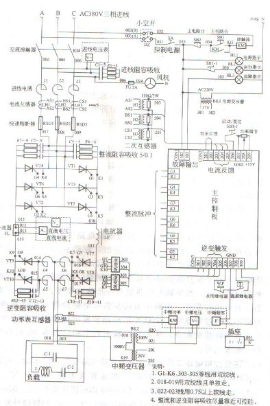
(1) Working principle of rectifier trigger. This control circuit uses a digital rectifier trigger circuit. Its structural feature is that the overflow of the counting pulse of the counter circuit is used as the trigger signal, and the phase shift of the trigger signal is completed by changing the frequency of the counting pulse. The basic working principle of the digital rectifier trigger circuit is shown below.
In the figure, there are three identical pulse triggering links for the three-phase AC voltage input. Each link includes: pulse generation counter, pulse channel selection circuit, 2-way pulse shaping amplifier circuit, reset circuit and 2 pulse transformers. Its working principle can be described as follows.
The control of the rectifier trigger circuit comes from the rectified output adjustment voltage Uk. The size of Uk is converted by the V/F circuit to form pulse signals of different frequencies. The pulse generation counter sends a pulse to the pulse channel selection circuit after overflowing according to the set value. The pulse channel selection circuit The circuit then divides the pulse into two outputs, and the phase difference between the two pulses is 180°. After the two-way pulses after phase separation are shaped and amplified, the corresponding thyristors in the three-phase fully controlled rectifier bridge can be triggered through the pulse transformer. Like other forms of phase-shift trigger circuits, digital trigger circuits also have a phase-shift reference point, which is taken from the zero-crossing point of the three-phase voltage. In the circuit, the synchronization signal circuit detects the three-phase zero-crossing points, and sends counter reset signals to the three pulse forming links corresponding to different zero-crossing points as the starting point of pulse counting, so that six double narrow pulse trigger signals with a phase difference of 60° can be output. . This time we will first talk about the working principle of medium frequency induction plus power trigger, and next time we will talk about the working principle of its inverter control circuit.


 en
en  cn
cn  jp
jp  ko
ko  de
de  es
es  it
it  ru
ru  pt
pt  vi
vi  th
th  pl
pl 


 GS-ZP-50