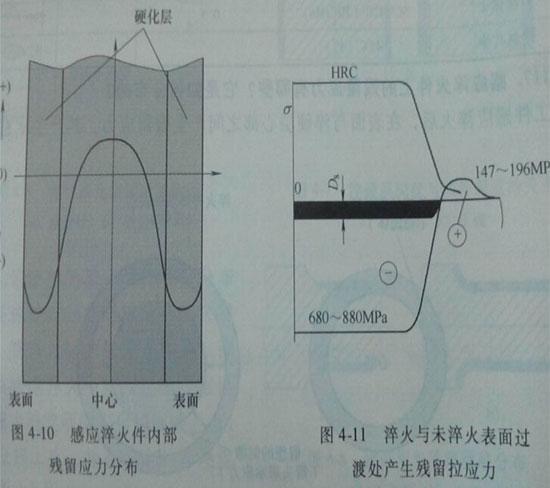
After quenching with a medium frequency induction heating machine, residual stress is generated between the surface of the workpiece and the core of the hardened layer. The schematic diagram of the generation is as follows:

Residual stress distribution of the workpiece after quenching by medium frequency induction heating machine
The schematic diagram on the left side of the above figure shows the state after heating is completed. When the workpiece is heated, the surface layer expands due to heat, but the surface layer is restrained by the cold core, resulting in plastic deformation. No stress is generated at this stage. The schematic diagram on the right side of the above figure shows the state after quenching and cooling. At this time, the cold core remains unchanged, but the surface layer undergoes martensitic transformation due to rapid cooling. The volume of martensite is larger than the original structure, and it is also a very hard structure. When it is restrained by the core, it cannot undergo plastic deformation. As shown by the arrows in the figure on the right, elastic deformation occurs between the surface layer and the core on the one hand, and they restrain each other on the other hand. It is conceivable that if the surface and the core are separated, a gap will form between the two, but in fact the two cannot be separated. Therefore, the expanded surface layer is restrained by the core and is in a compressed state, while the core is in a tensile state, on the contrary. The compressed surface layer and the tensile core finally maintain a balanced balance, and the stress generated is called residual stress. During induction quenching, the residual compressive stress generated in the surface layer (expressed by "-") and the residual tensile stress generated in the core (expressed by "+") are generated. The reason why the workpiece quenched by the medium frequency induction heating machine has high fatigue strength is essentially because of the residual compressive stress in the surface layer. Figure 4-10 below shows the residual stress distribution inside the workpiece after quenching.

Residual stress distribution inside the workpiece after quenching by medium frequency induction heating machine
As can be seen from Figure 4-10 above, the residual compressive stress on the outermost surface is not the largest, which is often caused by decarburization on the outermost surface. Under short-time induction heating conditions, the maximum residual compressive stress on the cylindrical surface is generally 80~100MPa, and the surface of gears and other special shapes is generally 30~80MPa. This residual compressive stress can improve the static load and dynamic load strength of the quenched workpiece.
When a medium frequency induction heating machine is used to quench the partial surface of a part, residual compressive stress is generated on the hardened surface, while residual tensile stress is generated in the transition zone between quenching and unquenching, as shown in Figure 4-11 above.
Residual tensile stress acts opposite to residual compressive stress, reducing the static and dynamic strength of quenched parts. The designer must consider that this part cannot be superimposed with other stresses to reduce the strength. For example, if the crankshaft journal is only quenched, the fillet part is originally a stress concentration point. If the residual tensile stress is superimposed, the strength of the journal will be greatly reduced. For this reason, rolling or quenching is used at the fillet of the journal to convert the residual tensile stress into residual compressive stress and improve the fatigue strength of the crank journal.


 en
en  cn
cn  jp
jp  ko
ko  de
de  es
es  it
it  ru
ru  pt
pt  vi
vi  th
th  pl
pl 


 GS-ZP-1200


